The end of Retrochallenge 2022/10
I have learned a lot about writing a assembler.
Last month I’ve been going through all my documentation and trying to describe how I came to get started with the 1-Bit microprocessor. The hardware, the cooperation between the address bus and the IO, how do you get multiple controllers to work with a 1 bit data bus. Connect the utility of the output of the Result Register to an input. Connecting an output to an input to create a memory bit. The set-up, operation, programming and testing of the assembler. All in all I really enjoyed this robot based on the 1 bit microprocessor mc14500b. I have learned a lot that I can continue with the next project.
For me, this is the end of Retrochallenge 2022/10.
After I have managed to control the outputs for the mc14500b with the help of the mc14599, I now want to read out the inputs in order to be able to use the statuses of the line following sensors in my program. For the inputs we use a mc14512b 1 out of 8 decoder. We see in the truth table that if we always make the Inhibit 0, then we can choose with the Disalble whether we take 1 of the 8 inputs to the Z output or whether the latter has a high impedance. This when we think about this we notice that this Disable connection can be connected -directly- to the Write of the mc14500b !! The Disable must be low to make the mc14512 active and if we want to write the data bus the Write output goes high, so this mc14512b is NOT selected.
socket for the mc14512b at the right
We connect the mc14512b to the 3-bit address bus from the Eprom, the data bus, and the Write. The output of the MC14500b of the Result Register (RR) we connect direct to X7 so that we can read the value of the RR on an input.
We also connect the outputs OUT-4 and OUT-5 to the inputs X4 and X5 so that we can use these as memory locations. We connect the line-following sensors to X0 and X1. The RC timer is controlled by OUT-6 and read by X6.
Here too I made the mistake of not connecting the Inhibit to the 0 at first. Because of this, the input selection was not reliable and it took me a while to find it. When I had connected the inhibit properly, the inputs worked well and I could test the 2 line full sensors, 2 memory bits and RC timer. This worked very well very quickly.
After this success I was able to get started with programming, especially to make an assembler. My goal is to create an onboard assembler that starts working when the ESP32 starts up. Using the SPIFFS we want to put the assembly program in the ESP32, after which it will be assembled, put in memory and after that the rset of the mc14500b will be released and the ESP32 will function as an Eprom emulator.
How does an assembler program work, I have no experience with this. How should that work. How do I read a file that is put in the SPIFFS file system. How do I read a line from this file. How do I convert a line of text into an 8 bit machine code? How do I deal with errors in the rules.
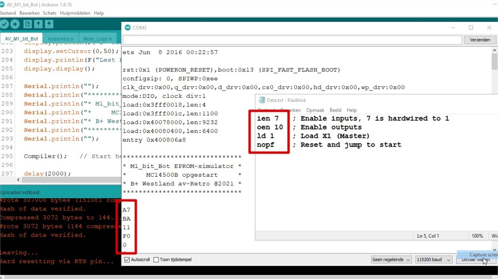
Using the above 4 lines I was able to parse each line into a byte of machine code. In the Arduino ino-file on github you can see in the program, with enclosed header files, how this is structured.
After a lot of errors, problems, extensions, searching, I got more and more works. How do I handle the errors that -may- occur in the rules. What do I do if there is an error in the assembly program. Finally I decide to give the WS2812 LED a different color, not to enable the reset of the mc14500b and to display an error code by the serial output (to a terminal program).
To write the assembler I learned a lot. I had a lot of fun with it.
And in the end it worked well.
After this i update the Github with the Arduino-ino file so the program is available:
For a robot you need inputs for the sensors and outputs for controlling the motors. If you are going to build or build a system, it is easier to start with the controls first. You can use LEDs for this instead of directly controlling motors. Then you can test your hardware in combination with your software. Instead of doing all kinds of difficult things, you can also just make an LED (output) blink. If an LED flashes, you can also do other things with it, but then you DO control how an output should be controlled on/off. And whether an LED or a real motor is connected to it, it does not matter.
mc14599b at the top
We connected the address bus from the Eprom emulator, the ESP32, to the mc14599b using the white/yellow wires. The -Write- line from the mc14500b is connected to the mc14599b by means of a blue wire, this is made high when we want to put the data from the data bus (the green wire) on an output. At first this didn’t work at all. If I wanted to make a certain output high, it didn’t work at all. An exit went on and off randomly, but not the way I wanted. After connecting my logic analyzer to the various lines, I understood even less. I sent everything fine but the mc14599b was NOT handling it properly. After a lot of searching, the Enable of the mc14599b turned out not to be connected to the write line. The mc14599b can be used for outputs or inputs. I only use it for outputs, so I connect the Write/Read connection, pin 10, to the 5 Vdc and use the CE, pin 8, for the write command. After having corrected this, the program ran and I saw the output become active at the desired moment. This forgotten connection took me over a day to search, but it has been found and I can continue with the entrances.
From a memory (usually an EPROM, but in our case an ESP32 serves as an eprom emulator) we send an 8-bit command to the mc14500b. This 8-bit command consists of 2 parts in my robot, a 4-bit machine instruction part and a 4-bit address part. So we are going to present an instruction to the microprocessor. If it is a read instruction, we select the address and read in the -data- entry. If the instruction is a -write- instruction, we send the -data- line to the selected address and activate the -Write- Flag. This -Write- Flag is not set with a read instruction. In fact, we use the -Write- Flag to determine whether we are addressing the inputs or outputs of the system.
Not many programming languages are available for the mc14500b microprocessor. I myself have decided to make my own (onboard)assembler, this will be discussed later.
The program counter and the addressing of the memory are not done in the microprocessor itself. There are no real possibilities to make jumps. What is often done is to use a special -Flag- to reset an external program counter. For example, the NOPF statement. Then the -F- output is connected to the reset of the external program counter.
Since we can’t make jumps, we have to use other techniques to skip certain program blocks. The IF-THEN(-ELSE) commands are quite possible.
Because there is only 1 register in the mc14500b of 1-bit, we also have to come up with other things for this. If we need a lot of extra memory, we can connect a 1K * 1 memory and make the address bus very wide. If we only need a few bits of memory, we can also connect an output of an mc14599b to an input of an mc14512. If we give an output a certain status, we can retrieve the status of the connected input later in the program and continue with this. This may be a bit of a strange idea, but it is very applicable.
In this way we can also make timers and counters. We connect an RC combination to an output and after the RC time has elapsed, the status of the input changes, so we know that a certain time has elapsed and for that time we skip a certain (program) block. This also applies to counters. We connect a counter to an output that we pulse every round in the sequence. And after a certain number of pulses, the output of the (hardware) counter that is connected to the input flips and we know that this number of pulses has passed.
The methods are a bit different, but we can create a program, make jumps, have memory places to store things, have timers and counters. So basically we have everything to build a complete working microcomputer system with which we can control a Robot.
What are more things we want to make related to our Robot. – ESP32 as EPROM emulator – Onboard assembler – All -Motorola- brand ICs – Create program in the Arduino IDE – Upload assembly file via SPIFFS – Nice OLED display with information on it
This is how we get started.
In the middle we see the mc14500b. From the ESP32, the 4 bit instruction bus (yellow) goes to the mc14500b. From the 555, in red, the Clock signal goes to the mc14500b. From the mc14500b the F-flag goes in purple and in white the Clock_ signal goes to the ESP32.
Now we can run de famous NOPO, NOPO, NOPO, NOPO, NOPO, NOPF program to see if our hardware is working correct with the software.
My robot has the mc14500b as microprocessor. This is a 1-bit processor, developed in 1977 by Motorola. At that time, there were already other processors such as the 8080 and the Z80, so why develop a 1-Bit microprocessor? For industrial applications they were looking for cheap solutions for the replacement of relay controls of automation systems. At the time, the 8080 cost $20 and the Z80 $50, and the mc14500b was marketed for $7.50. The costs could be kept low because the processor was built with very few transistors, only 500. The Z80 was made up of 8500 and the 4004 of 2250 transistors. The nickname for the mc14500b was therefore the Industrial Control Unit. Due to the rapid development in technology, the mc14500b was quickly overtaken by other techniques and other processors such as the PIC that came on the market a few years later. The MC14500 has a 1 bit data bus, a 4 bit instruction bus and depending on the required addresses a 4, 8 or 12 bit address bus. In addition, it has 1 internal register of 1 bit. The mc14500b has no program counter, making address jumps is difficult but not necessary as we will see later.
ALU
All operations are performed on the data bus, we read and write to this bus. When we write, we also activate the -Write- output so that we can activate the I/O with it
There are 16 instructions available, 3 of which are almost never used.
The instruction set is compact and very powerful. It is very suitable for controls. The mc14500b is a microprocessor especially for hardware people.
On 1 Oktober 2022 has been held the Roborama 2022. This are a couple tasks for little robots build by hobbist of the Dutch HCC. This year I have build a new robot around the microprocessor mc14500b. This is a real 16-pins Motorola microprocessor with a databus of 1-Bit (!!) and is made in 1978. I do the match and I am able to accomplish the run.
Last weeks there are new developments around the RetroChallenge. Mark Sherman restart the RetroChallenge with succes. http://mwsherman.com/RCR/2020/04/ So we can do our job again.
Now it begin.
In the year 1999 i follow a course at [Dirken opleidingen], a technical education institute located at Arnhem, the Netherlands. This course was a part of mine change in work area. Before this course I was working in the greenhouse industri as a grower / owner of a greenhouse complex in Westland, the Netherlands. I sold my greenhouse and have done a 1 year technical education at [Dirksen opleiding] to become a technical service enginer. After this course a become a job as service enginer in the greenhouse computer installations.
But during this year of courses I also do the course [Microcomputer] and [Microcomputer interface technics]. For this course we use a singelboard computer to learn assembly programming and to understand the microprocessor technics. This singel board computer was the Microprofessor-1b. About the MPF-1b, and how to program this I will work in thes RCR2020/04.
The MPF-1b is a singelboard computer build around the Z80 microprocessor. It is build around 1981 in England by the company MultiTech Industrial Corp, now Flite, but the MPF-1b is still in production and available: http://flite.web-feet.co.uk/micro-controllers
I have send my Participation of the RC2019/10 to the judge, Michel. My subject is to program and load the Z80 MicroProfessor-1B from a W10 computer/laptop.
The MicroProfessor-1B is a Single Board Computer with a Z80 processor, a hexidecimal keypad and a 6*7segments display. In the 80’s – 90’s It was a great learning system to understand the working of microprocessors and programming. The program you type in on the keypad. The program’s you could store on a casette tape and also restore from an casette tape. Later there where Z80 assembylers so you can type your program on a PC and then send to the MPF-1B. These assembylers works under DOS and send the binaire file by the COM-/printerpoort to the MPF-1B. Nowday these programs are not working and the most computers have no COM-/printerpoort so when we whant to program our MPF-1b we need an other solution.
Let’s program and load our MPF-1B Z80 by a W10 computer/laptop is my goal for the RC2019/10.
The RetroChallenge 2019/10 is moved to next spring. So the next RetroChallenge is in 2020/04.
The last couple weeks I have spend a lot of time to study datasheet’s, programming OCCAM, debugging with a logic analyser en use my soldering Iron to fix some hardware issues. But most of the time i have FUN !!
I can read the INPUTs and write to the OUTPUTs of the IMS C011, the Transputer IO-Link interface.
A small step for humanity, but a big step for me 🙂
I have reached my goal for the RetroChallenge 2019/03
This is very nice because the last part of the month I am not at home. So for my this is the end of RetroChallenge 2019/03.
After controlling the output of the IMS C011 Transputer IO-Link interface it is now time to take a look at the input’s. Before my friend can build a Robot based on a Transputer system we must can control output’s but also read input’s from sensor’s. So let’s take a look at the Input’s of the IMS C011 Transputer IO-Link interface.
I wrote a little program how i think how it must be work’s.
But nothing happens (ofcourse ?) At saturday 16 March there was an meeting of the HCC!Retro computer club. This means Hobby Computer Club, section Retro computers. This meeting was held in Bilthoven the Netherlands. HCC!Retro website
During this day we have a lot of talk about Vintage computer systems, core memory, Bubble Memory and other old hobbycomputer stuff. Also we have a little look at the transputer I carryed with me. When I ran the program noting happen, but when a friend of mine take a look at the IO-Interface print I have build he take a look at the backside of the print. On that moment a saw some numbers comming on the screen ??!!
Wait !! What is happening here, then I remember the handshake signal’s. The Ivalid was not connected and this is high impedance so when you are moving your hand in the area “sometime’s” you get a high strobe on the input and then you get a value in your system.
I took a nice little wire and use this as a strobe signal to the +5Volt. When i touch the Ivalid then the value of the dipswitch would be displayed on the screen. Victorie !!!
Next step is to make the system a little bit more better working. I decide to connect the OVaild to the IValid so when i get data for the output, then also the value from the dipswitches goed into the IMS C011 to the Transputer.
Now I read the values of the dipswitch very good.
Lessons I have learned about this: There are 4 handshake line’s on the IMS C011. Think about them carefull !