When you made a program in OCCAM you work with channels. These channels could be software in a Transputer chip OR hardware to an other Transputer chip. But how you tell the “OCCAM program” that he must connect / send the informatio to a fixed IO-Link at the Transputer. I could not a good feeling about this situation. After reading a lot of artikels I don’t understand.
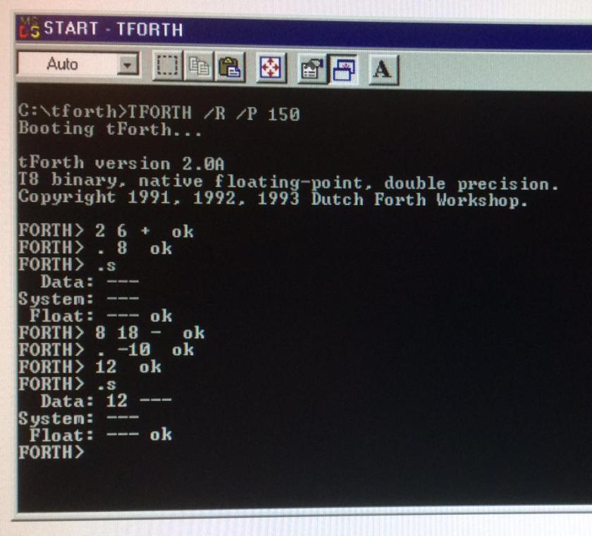
During building the IO-Link interface around the IMS C011 i get an book in my hands from Ian Graham and Tim King with the name [The Transputer Handbook] I “walk through” and suddenly i read a nice chapter about the command PLACE .. AT ..


This little tekst open my eyes and slowly i understand how to send a value by a specifyed channel to an IO-Link with an inferface connected. So i write my first little program to send a value to my LED-print. Ofcourse this was not good an i get the wrong value on the LED-bord, but WHY ??

So i start debugging. I found that the Link-speed between the Transputer and the IMS C011 Link Interface was different. The Transputer runs on a Linkspeed of 20 Mbit but the IMS C011 was configurated at 10 Mbit. After using my soldering Iron to correct these mistake i do the test again. But now i see even not lit up a LED ?? What’s wrong now ?? Let’s read the datasheet of the IMS C011 again. There is written that there must be a QAck before ther comes an Ack to the Link back to the transputer. After connecting the QValid to the QAck still no burning LED’s ??
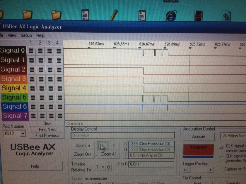
After hookup an logic analyser i get very nice information, see line 1. There comes more then 1 pulse each time i send a byte. Slowly i understand, i don’t send a byte, I send an Integer, that are 4 byte’s !! And the last byte is displaid on the LED’s. So after shifting to left by 24 bit’s I get a wanted value on the LED’s.
Now I am also able to run the KITT-light. See the YouTube link below.
What’s Next, the output is ready, so let’s start to take a look at the input !!