Programming the MPF-1b

How to program, Hardware and Software.

For the course with the MPF-1b we get from [Dirksen opleidingen] a special EPROM with a changed “loader”. With this special loader we could recieve a binary file by the microfoon input to the MPF-1b. Normal you connect the MIC and SPK connector to the casette recorder to record or play-back programs from or to the MPF-1b. They have changed the loader so it is being capable to load binairy files. On the PC, under DOS you can edit a asm-file and compile this by Z80-assembler. After this you could load the program by the serial COM-port to the MPF-1b. Below is the first part of the overvieuw for the hardware of the MPF-1b. There also 2 pdf’s with the more complete hardware, exclude the PIO part of the system.Schema_jpg

Schema_1   

Schema_2

The big problem with the system for the course is that the delivered program works onder DOS and not in the DOS-box for Windows-10. Also the COMM-cable is a little bib a problem, the most computers and laptop’s don’t have a serial port anymore.

So, for working with the MPF-1b under W10 first a have take a look for a new compiler, then I do a search for the communication cable from computer to the MPF-1b and at last I need a communication / loader program running under W10.

At the internet I found a very nice website with a nice compiler, called sb-assembler (https://www.sbprojects.net/sbasm/) With this assembler you could choose a lot of processors fir with you could write program’s. This works with/under Python. When you add a number of line’s to let the program know’s how to handel your file it works perfect for me. Great thanks to San Bergmans for this nice tool. First point is solved !

For the communication cable between my computer (laptop) and the MPF-1b we must think about a couple things. The “normal” voltage levels on the COM-port of the “old style” PC’s are -12 and +12 Volt. So on this moment the MPF-1b can handle this.  If I buy a USB to Serial convverter cable we must convert this +5 Volt to -12 and +12 Volt. In this case I have im my storage a lot of max232 converter IC’s. Together with 4 Elco’s of 10uF – 16 Volt I made a little converter. So I bring  the 5 Volt from the USB to Serial converter to a good -12V and +12V RS232 level. Second point is solved.

The third point is a loader program. In good “old school” Visual Basic 6.0 I start writing a program to open the INTEL-hex file produces by sbasm.

Loader

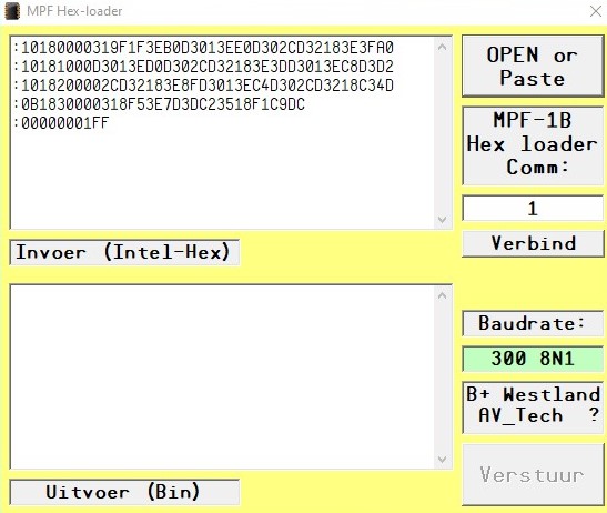
First you open the file in the Loader program, the you connect to the right serial-COM-port and then you can upload [Verstuur] the program.

I want to collect the next information, EPROM data, converter cable diagram and the source code for the loader program and put all this information on my GitHub.


RCR2020/04 has begin

Last weeks there are new developments around the RetroChallenge. Mark Sherman restart the RetroChallenge with succes. http://mwsherman.com/RCR/2020/04/  So we can do our job again. 

Now it begin.

In the year 1999 i follow a course at [Dirken opleidingen], a technical education institute located at Arnhem, the Netherlands. This course was a part of mine change in work area. Before this course I was working in the greenhouse industri as a grower / owner of a greenhouse complex in Westland, the Netherlands. I sold my greenhouse and have done a 1 year technical education at [Dirksen opleiding] to become a technical service enginer. After this course a become a job as service enginer in the greenhouse computer installations.

But during this year of courses I also do the course [Microcomputer] and [Microcomputer interface technics]. For this course we use a singelboard computer to learn assembly programming and to understand the microprocessor technics. This singel board computer was the Microprofessor-1b. About the MPF-1b, and how to program this I will work in thes RCR2020/04.

The MPF-1b is a singelboard computer build around the Z80 microprocessor. It is build around 1981 in England by the company MultiTech Industrial Corp, now Flite, but the MPF-1b is still in production and available: http://flite.web-feet.co.uk/micro-controllers

On internet is also a lot of information available about the MPF-1b, http://electrickery.xs4all.nl/comp/mpf1/

RetroChallenge 2019/10 –> 2020/04

I have send my Participation of the RC2019/10 to the judge, Michel. My subject is to program and load the Z80 MicroProfessor-1B from a W10 computer/laptop.

The MicroProfessor-1B is a Single Board Computer with a Z80 processor, a hexidecimal keypad and a 6*7segments display. In the 80’s – 90’s It was a great learning system to understand the working of microprocessors and programming. The program you type in on the keypad. The program’s you could store on a casette tape and also restore from an casette tape. Later there where Z80 assembylers so you can type your program on a PC and then send to the MPF-1B. These assembylers works under DOS and send the binaire file by the COM-/printerpoort to the MPF-1B. Nowday these programs are not working and the most computers have no COM-/printerpoort so when we whant to program our MPF-1b we need an other solution.

Let’s program and load our MPF-1B Z80 by a W10 computer/laptop is my goal for the RC2019/10.


The RetroChallenge 2019/10 is moved to next spring. So the next RetroChallenge is in 2020/04.


Conclusion RC2019/03

The last couple weeks I have spend a lot of time to study datasheet’s, programming OCCAM, debugging with a logic analyser en use my soldering Iron to fix some hardware issues. But most of the time i have FUN !!

IMG_5459

I can read the INPUTs and write to the OUTPUTs of the IMS C011, the Transputer IO-Link interface.

A small step for humanity, but a big step for me 🙂

I have reached my goal for the RetroChallenge 2019/03

This is very nice because the last part of the month I am not at home. So for my this is the end of RetroChallenge 2019/03.

–END of RC2019/03–


Reading INPUT’s from the IMS C011

After controlling the output of the IMS C011 Transputer IO-Link interface it is now time to take a look at the input’s. Before my friend can build a Robot based on a Transputer system we must can control output’s but also read input’s from sensor’s. So let’s take a look at the Input’s of the IMS C011 Transputer IO-Link interface.

I wrote a little program how i think how it must be work’s.

hello_e

But nothing happens (ofcourse ?) At saturday 16 March there was an meeting of the HCC!Retro computer club. This means Hobby Computer Club, section Retro computers. This meeting was held in Bilthoven the Netherlands.  HCC!Retro website

HCC!Retro

During this day we have a lot of talk about Vintage computer systems, core memory, Bubble Memory and other old hobbycomputer stuff. Also we have a little look at the transputer I carryed with me. When I ran the program noting happen, but when a friend of mine take a look at the IO-Interface print I have build he take a look at the backside of the print. On that moment a saw some numbers comming on the screen ??!!

Transputer_lezen

Wait !! What is happening here, then I remember the handshake signal’s. The Ivalid was not connected and this is high impedance so when you are moving your hand in the area “sometime’s” you get a high strobe on the input and then you get a value in your system.

I took a nice little wire and use this as a strobe signal to the +5Volt. When i touch the Ivalid then the value of the dipswitch would be displayed on the screen. Victorie !!!

IMSC011_input

Next step is to make the system a little bit more better working. I decide to connect the OVaild to the IValid so when i get data for the output, then also the value from the dipswitches goed into the IMS C011 to the Transputer.

Now I read the values of the dipswitch very good.

Inp_Value.JPG

Lessons I have learned about this: There are 4 handshake line’s on the IMS C011. Think about them carefull !


Software for controlling the IO-Link Interface.

When you made a program in OCCAM you work with channels. These channels could be software in a Transputer chip OR hardware to an other Transputer chip. But how you tell the “OCCAM program” that he must connect / send the informatio to a fixed IO-Link at the Transputer. I could not a good feeling about this situation. After reading a lot of artikels I don’t understand.

During building the IO-Link interface around the IMS C011 i get an book in my hands from Ian Graham and Tim King with the name [The Transputer Handbook] I “walk through” and suddenly i read a nice chapter about the command PLACE .. AT ..

This little tekst open my eyes and slowly i understand how to send a value by a specifyed channel to an IO-Link with an inferface connected. So i write my first little program to send a value to my LED-print. Ofcourse this was not good an i get the wrong value on the LED-bord, but WHY ??

First_Prog.JPG

So i start debugging. I found that the Link-speed between the Transputer and the IMS C011 Link Interface was different. The Transputer runs on a Linkspeed of 20 Mbit but the IMS C011 was configurated at 10 Mbit. After using my soldering Iron to correct these mistake i do the test again. But now i see even not lit up a LED ?? What’s wrong now ?? Let’s read the datasheet of the IMS C011 again. There is written that there must be a QAck before ther comes an Ack to the Link back to the transputer. After connecting the QValid to the QAck still no burning LED’s ??

IMG_5462.JPG

After hookup an logic analyser i get very nice information, see line 1. There comes more then 1 pulse each time i send a byte. Slowly i understand, i don’t send a byte, I send an Integer, that are 4 byte’s !! And the last byte is displaid on the LED’s. So after shifting to left by 24 bit’s I get a wanted value on the LED’s.

Now I am also able to run the KITT-light. See the YouTube link below.

KITT light on Transputer

What’s Next, the output is ready, so let’s start to take a look at the input !!


Goal and Hardware for RetroChallenge 2019/03.

During the RetroChallenge 2019/03 my goal is to build and program a system to control outputs and read inputs from a transputer system.

For this purpose i buy a couple IMSC011 Link adapters. These link adapters as speciale made for connecting to an Transputer Link for connecting handware. This could be a interface to an computersystem, like an IBM or SUN or VME system for loading software, or to other hardware to control all different thing’s.

In an former RetroChallenge I build an inferface to an ISA-slot for connecting an Transputer to an PC for loading software, and now I want use this same Link adapter in an other modus to connect some LED’s and switches to control and measering.

IMSC011_data

The datasheet for the IMS C011 could be found on several places on the internet so this is the startpoint of our Challenge. Reading and understanding the datasheets. This Link Adapter could be used in 2 differend modus. The second modus as an businterface, to connect an ISA-bus for example. The first modus is a Peripheral interface modus. Then you have 8 output’s and 8 input’s and fully handshake control. And this is the modus we go to use.

After building a nice little print a have the hardware to start with my project.

Print

RetroChallenge 2019/03

Next month the RetroChallenge 2019/03 start’s,   http://www.retrochallenge.org/    I wil be a partner of this Challenge. My goal is to controll input’s and output’s with a IMSC011 interface chip for the Transputer. A couple year’s ago I buy some of them and now i want to use them to controll some LED’s and read some switches by the language OCCAM from a real transputer.

Happy RetroChallenge 2019/03IMSC011

Adresdecoding the CSA Transputer interface.

I have get a question about the picture of the interface I have build.

Adress

In my interface I have hardwired the adres 150 Hex for the Interface and 160 Hex for the System Signals. The question about the schema for the IMSC011 in place of the IMSC012. I have just take the datasheet’s for the both part’s and connect the right signal to the right place. So there is no different schema for the IMSC011

Explore the Transputer netwerk by iSpy.

I have to borrow 2 Transputer cart’s with 2 Tranputters on each cart. I look’s me nice to see if I can connect them together to a netwerk and take a look how a program see this. In my situation it is not always easy to connect a monitor, keybord and mouse to the Window’s 98 PC. Or some time’s I want to work from the living room and the computer stands on the zolder. So I decide to work remote on this PC. But then come’s the “big” problem. Find a program to work remote with a Windows-98 PC. After a lot of searching on internet I found the program Radmin. The old server version of Radmin, version 2.1, run on Windows-98. So i installed it en now I can reach my PC with the selfbuild Transputer inferface connected to 4 transputer processors.

Radmin

Special for exploring the Transputer netwerk there are some worm-program’s. You load them onto the Transputer network and they give a reslut of the connection’s between the different Transputer processor’s on the network. This iSpy program is original from INMOS, but a lot of people have modified this for tehr one. So found on the website http://www.geekdot.com/category/software/transputer-software/ the TTK, The Transputer Tool Kit. This is a collection with test program’s for the Transputer, also some version’s of iSpy are include. When unzipping en starting the iSpy232 I get a very nice result of my 4 transputer’s connecting to the selfbuild ISA cart. The author of some program’s is Andy, Andy Thanks !!

Transputer_line
4 Transputers in line

First i put 4 Transputers in line. This show a nice result. The next network was a tree. One link of the Host-Transputer is connected to the ISA-interface and the other 3 links are connected to 3 different Transputers. This is build as follow.

Transputer_tree
4 Transputer Tree

And give the next result when I start iSpy:

iSpy_tree

This is a real Transputer netwerk. Oke, now I need a real program to run on it.

Hackerspace_B

On monday 30 Oktober there was a little meeting of the Hackerspace “B+ Westland” at my place. We talk about the result of my work with Transputers, study to a “new purchased” Transputer interface and have a lot of fun.


Next challenge is to understand the OCCAM toolkit workflow. Normally I work with microcontrollers, in that case you don’s have a compiler, linker, configer and a make program. Just compile and load the program in the microcontroller. Now I must follow a different path. I hope I should understand this.

For me this is the -END- of the Retrochallenge 2017/10. I had this month only a spare time for this to reach my goal. So in the future time I go ahead with Transputers to understand the system and how to program them.

I have a lot of fun to work with Transputers and also with the talk’s with the people around me about Transputers.


-This is the END of RC2017/10-